The Loki Prototyping Plank

Time to introduce another of the initial set of Loki planks, the Prototyping Plank.

Every platform needs a prototyping board, and Loki’s no exception. It may not be exciting, but it’s certainly essential.

Besides the expected grid of prototyping holes, this one has some important features:

  • Breaks out 8 GPIO lines
  • Dedicated area for thru-hole DIP chips up to 24 pins wide
  • Convenient 3v3 power and gnd buses
  • General prototyping area
  • Square pads for easy soldering of SMT passives
  • Dedicated area for right-angle edge connectors on the left side of the board
  • Breaks out all power/config header pins

There’s not a great deal else to say about this one. I’m certain people will find it useful, though.

Comment

Display Plank demo: Conway's Game of Life

Just a short post today. I’ve been writing some libraries and demo apps for the Loki, and first up is the Display Plank. Here’s a quick demo showing it running Conway’s Game of Life:

That’s running at nothing like full speed - I slowed it down a lot so us mere humans could comprehend it.

This was just hacked up in a hurry, but I’m currently working on a library for the display so it’ll be really easy to use in your own projects. It’ll make use of the PSoC’s DMA facilities, so it will be a lot more efficient, too - just pass in a buffer representing the display, and it will write the whole thing out to the display with no involvement from your code or the CPU.

Keep an eye out for more details on the peripheral and the inner workings of the demo soon!

Comment

Plug and Play configuration with Loki

Previously, I wrote about how Loki avoids pin conflicts by remapping IO pins with surface mount headers on each expansion plank. I mentioned at the time that this can lead to some confusion figuring out which plank pins correspond to which microcontroller pins, and hinted at a solution. Today, we’ll take a closer look at how that solution works.

The problem, if you recall, is that the Loki is set up such that each plank takes the first available pins; this means that the microcontroller pins your plank is connected to depend on what other planks are in the stack below it. Rearrange the planks, and the pin assignments change. This isn’t a problem from a hardware point of view - any Loki pin can perform any function - but it can be hard to keep track of.

Loki solves this with a configuration system. Much like the Beaglebone, each expansion plank has an onboard EEPROM that contains configuration data. This data includes its name URL, optional serial number, flags, and most importantly, a description of which GPIO pins it uses. Each pin that’s used is given a name determined by the plank. Likewise, the Loki has an onboard EEPROM storing the pin names of the Loki itself.

With EEPROMs on each plank, we can identify planks at runtime, and with the pin names on the Loki and the pin names on the expansion boards, we can build up a nice convenient table, allowing users to see at a glance which pin is mapped to which plank. This still ignores the sticky issue of addressing, however. Supposing we use I2C EEPROMs - how do we ensure each plank’s EEPROM has a unique (and predictable) address? We could use jumpers, like BeagleBone capes do, but this seems rather manual. The consequences of setting the jumpers wrong are a lot worse for the Loki than they would be on the Beaglebone, too - the pin mappings would be inaccurate. How can we give each EEPROM a unique address, without manual intervention and undue complexity?

The answer comes to us from computer science, in the form of the Linear Feedback Shift Register or LFSR. An LFSR is a way to generate a sequence of numbers that goes as long as possible without repeating. Even better, LFSRs are really simple to generate, and can be made using a single XOR operation to generate each subsequent bit!

A concrete example will be more enlightening. Suppose we want to generate all possible 3-bit addresses. A maximum length LFSR for this has 3 bits of state, and generates the next state by taking the two most significant bits and XORing them together. Suppose we start with 001. We XOR the two most significant bits together (0 XOR 0 = 0) and add them to the end, getting a new state of 010. Repeating, we then get 101, 011, 111, 110, 100, 001. Note that we stepped through every single non-zero 3-bit number before coming back to our starting point of 001.

Using this in Loki is quite straightforward. The smaller Loki expansion header has three address pins. On the Loki itself, these are hardwired to 0, 0 and 1. Each plank connects the incoming address pins directly to its EEPROM’s address pins; it also shifts them left by one - so A1 becomes A2 and A0 becomes A1 - and uses a single XOR gate IC, the 74HC1G86 to generate the new A0 by XORing A1 and A2 together. Thus, the next plank in the stack sees the next value in the sequence, ensuring we can stack up to 7 planks without any repeating addresses. The XOR IC and the EEPROM (a CAT24C32 or larger) together cost less than $0.50 in quantity, so this adds a negligible cost to the average expansion plank. Here’s an example schematic for the relevant part of an expansion plank:

This system has incidental benefits as well. In addition to providing a general purpose I2C bus to all planks independent of the GPIO pins, it also provides a way for planks to attach to it without risk of address conflicts. As long as the I2C ICs they use have a different fixed prefix to the EEPROMs (which use the 7-bit prefix 0x50), they can use the same address pins for their own ICs.

The end result of this is a rather nice plug-and-play system that Just Works. I’m currently working on the bootloader host software, which together with the bootloader, can autodetect all the expansion planks installed on a Loki, and present you with details of each, along with an accurate pin mapping from microcontroller pin to plank pin, with useful pin names. Keep an eye out for a demo of it soon.

Comment

The Loki Sound Plank

Time for a look at another one of the initial expansion planks for the Loki: The Sound plank.

This plank takes advantage of the PSoC processor’s built in analog functionality to offer audio input and output options few microcontroller platforms can offer - at least, not affordably! The plank supports two stereo line jacks - one for line level output, the second for either input or output - and a 1W mono amplifier that can drive small speakers. It also has an IR receiver module as an option.

The plank takes 6 IO lines: Two for each line jack, one for digital volume control of the amplifier, and one for the IR receiver. As you can see from the photo, it doesn’t need very many components at all: a couple of film capacitors on each jack provide DC blocking, while the line in has protection diodes to protect the microcontroller against overvoltage. The amplifier is a single chip, the TDA7052A. It provides a 1 watt mono amplifier with an absolute minimum of external components. The speaker output is provided on a screw terminal at the bottom of the board.

All of this is complemented beautifully by the PSoC’s built in analog features. Analog features vary from chip to chip in the PSoC 5 range, but all have at least one ADC and one DAC; most have 2 or more DACs. In addition, most of the line have configurable analog blocks, which can be configured to act as programmable gain amplifiers and as sample-and-hold units, amongst other functions. Finally, most of the line have dedicated opamps that are accessible both internally on external pins.

When placed at the bottom of the stack, the Sound Plank is configured such that the outputs of two of the dedicated opamps are connected to the line out jack. This means the Loki can provide a very low impedance line output, perfect for good quality audio. Even when elsewhere in the stack, or connected to a processor that does not have dedicated opamps, the built in analog hardware still provides a good analog path.

Once connected, the user has a lot of options. The configurable analog blocks can be set up as sample and hold devices, allowing a single DAC to drive multiple channels, or the outputs can be driven directly from multiple DACs. PWM can even be used, if desired - all configured inside the chip. On the input side, the ADC can be configured to sample alternately from each channel at anything up to 700k samples per second.

All up, the Audio Plank will provide an exceptionally flexible solution for simple audio input and output on the Loki.

Comment

How Loki avoids pin conflicts

In an earlier post, I mentioned that Loki has a novel way of avoiding the pin conflict issues that plague other stackable expansion board systems. Today we’ll take a closer look at just how that works.

Most stackable expansion systems, such as Arduino, use long-tail thru-hole headers, that connect directly from the receptacles on the top of the board through to the pins on the bottom. These are convenient - though surprisingly hard to come by - and straightforward, but have a major issue: stacked boards must avoid using the same pins as each other, or they’ll be incompatible. Worse, there’s no good way for a shield designer to pick pins that won’t conflict, other than picking specific other shields to ensure compatibility with. Every user has to check carefully before purchasing a shield to ensure it won’t conflict with the other ones they want to use. Aside from being a hassle, this limits opportunities, making otherwise well suited expansions unusable.

There must be a better way, right? Fortunately, there is, and Loki implements it. Here’s how it works: Instead of using thru-hole stacking headers, Loki uses surface mount headers on the bottom, and surface mount receptacles on the top. Common signals such as power, ground, and the I2C bus are passed straight through, bottom to top. IO pins, however, are handled somewhat differently.

Instead of using any pins, each plank uses the first few pins from the GPIO bank. Then, it routes the remaining pins on the bottom header to the top, shifting them up to fill the ‘gaps’ left by the pins it consumed. So if a plank needs 4 pins, it will use pins 1-4 for itself, then connect the incoming pin number 5 to outgoing pin 1, 6 to 2, 7 to 3, and so forth. In this fashion, because used pins are never passed through, every pin can only ever be used by a single plank, and thus no plank has to worry about conflicts. You can keep stacking additional planks until you run out of IO pins!

Of course, the reality is slightly more complicated than the theory, but only a little. A plank that needs to use a lot of IO pins could have some difficulty cleanly routing the remaining pins to the first headers on the top side, so Loki splits the pins into two independent banks, consisting of the first half and the last half of the pins. A plank must take an equal number of pins from each bank. This simplifies the routing somewhat, while still preserving the flexibility. It’s also possible - though uncommon - for a plank to take pins other than the first ones in a bank. This limits where in the stack the plank can practically be placed, but still works fine: the plank just ‘shifts up’ the remaining pins to fill the gaps.

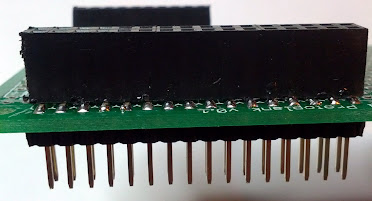
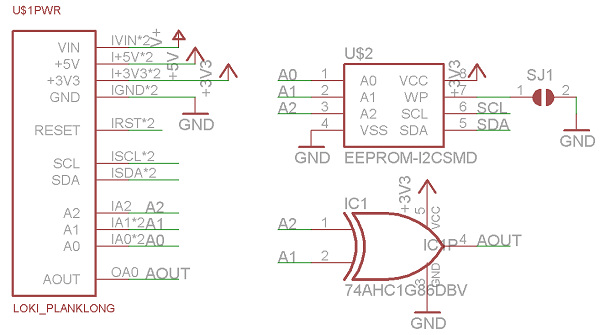
Here’s an example header layout for a plank that uses one pin from each bank:

As you have no doubt noticed from the photos, Loki has two expansion headers. The one on the top, a 2x16 header, contains all 32 GPIO pins, and uses the scheme described above. The one on the bottom, a 1x10 header, carries the power rails, ground, reset, the hardwired I2C bus, and a few other control signals we’ll go into later.

If you’re curious to learn more, or start planning out your own expansion planks, a preliminary specification for planks is available here. Beware that it may change before 1.0 - so if you are intending to make a board, get in touch first!

Some of you may be thinking that this system, ingenious though it may be, could lead to some confusion regarding which microcontroller pins are assigned to which plank pins, and you’d be right. Loki has a clever solution to that conundrum too - the details of which will be revealed in a future blog post.

Comment

The Loki Display Plank

Today we’ll take a quick look at one of Loki’s initial expansion boards, the display plank.

The display plank is a straightforward user interface plank, featuring an 84x48 dot matrix LCD display with backlight, and a 5-way (4 directions plus center click) digital joystick. It takes up 8 GPIO pins from the Loki, and it’s a “top plank”, meaning nothing else can be stacked on top of it.

I wanted this to be a substitute for the expansion boards featured in other embedded systems that feature a 16x2 character display. I figure that a simple graphic LCD will be a lot more interesting and versatile, and no harder to drive with the right libraries.

The display is worth a closer look. It’s an integrated module originally designed for the Nokia 5110 mobile phone, which makes it a bit on the venerable side, but with the significant advantage that it’s now really affordable - in bulk, it can be obtained for less than $1 per display, a price that’s hard to beat. I think of it as the Casio F91W of displays. Breakout boards are available from places like SparkFun, but I opted to build it directly onto the plank, to save money and improve the form factor.

The integrated controller on the LCD is the PCD8544, and speaks SPI, with an additional command/data selector pin. The protocol is well documented and quite straightforward. One of my first todos after getting the bootloader host finished and the alpha boards made is to write a library for this in PSoC creator, so that the display can simply be memory mapped and written to by blitting directly to memory, which should make using it super-easy.

The display attaches to the board with four metal clips; slots on the plank accommodate these and hold it in place. Electrical connections are via a flexible connector on the back; they simply make contact with bare pads on top of the PCB, no soldering required. If you’re building your own, bear in mind that a standard 1.6mm PCB is far too thick; use 1.0mm FR4 instead.

The display itself doesn’t include the backlight; it’s up to the host to provide that. I’ve done this with four 0805 white LEDs behind the module, which light it up nicely. It’d be easy to trade these out for other colors, too. An n-channel MOSFET gives the Loki control of backlight illumination.

Finally, the joystick. This is a part I picked up in bulk from China, courtesy of a good friend, and it works pretty much how you’d expect: 5 switches, with a common pole between them. The switch is connected with the common pole to ground, and the 5 switches connected directly to Loki IO lines; it’s up to Loki to pull these high using the built in pullups.

All in all, the display plank is a flexible board for basic user interaction, and I hope to be able to provide it at a much lower price than most similar expansion boards using character displays. I think this is going to make for some great demo apps, too - Snake, anyone? If you’ve got an idea for a great way to show the plank off, don’t hesitate to leave a comment, too!

Comment

Social media stuff

I’ve set up accounts for Arachnid Labs on Google+ and Twitter. Follow them if you’d like to keep up to date with Arachnid Labs’ latest developments, and progress on Loki!

Comment

Introducing Loki

Time to unveil Arachnid Labs’ first project!
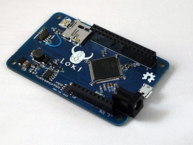
Loki is a microcontroller development board based on Cypress’s PSoC 5 processor. What makes the Loki unique is the combination of this very capable and unusual processor with a truly novel design for the expansion system. The PSoC is a uniquely capable processor, consisting of an Arm M3 core with a flexible frontend that incorporates “universal digital blocks”, which can be configured to implement almost any imaginable peripheral, coupled with a flexible routing system that lets you route any IO pin to any function. Loki builds on this, with a unique stacking expansion system that ensures that you can stack any expansion boards - or ‘planks’, in Loki terminology - up to the limit of the available IOs without having to worry about pin conflicts.

The end result of all this is a microcontroller platform that leaps past past your average Arduino clone, allowing you to create more interesting and involved projects, while spending less time messing around with protoboards and bitbashing, and more time on the parts of your project that matter to you. Cypress’s PSoC Creator IDE provides a powerful environment in which to develop your code, with high level easy to understand APIs, and a graphical digital design tool for configuring the programmable logic components, while the flexible expansion system lets you combine any expansion planks you need to get your project working. The PSoCs configurability means less glue logic and fewer external components, too, which will mean cheaper and more flexible expansion planks than other systems. For example, the analog audio expansion plank provides stereo line in and out with only a few passive components, relying on the PSoC’s built in analog functionality to do the heavy lifting.

In the next few days we’ll go into more detail about the Loki architecture and the PSoC, but today I’d like to cover the basic specs and my vision for the system.

Read more

Welcome to Arachnid Labs

Welcome to Arachnid Labs! We’re a one-man outfit based in London, England, and we’re currently gearing up to provide a bunch of interesting Open Source Hardware kits and projects. Keep an eye out in coming days for lots of technical details on the first of these.

The man behind the lab is Nick Johnson, who you may recognize from his regular Hack a Day appearances for projects such as iZac the android bartender, the sand plotter, the advice machine, and the 7400 logic FPGA.

Comment