
While minimatrix is in principle a pretty simple device, there’s a surprising amount of detail that goes into getting it right - and some interesting lessons to be learned in designing and programming it. I thought I’d detail a few of them for the benefit of anyone building something similar - or simply for interest.
#Minimatrix schematic Here’s the complete minimatrix schematic:

As you can see, it’s fairly straightforward. The LED matrix is driven directly by the attiny; other than that we only have the IR receiver and button - which use the same GPIO pin - and the battery. The microcontroller is an ATTiny4313, which has - just barely - enough GPIO pins to drive the matrix.
There’s good reasons for assigning the pins the way they are here - and we’ll get into them a bit more in the section on driving the matrix, below.
PCB layout is also fairly simple, though we have a serious lack of space on something so small. A double sided approach is necessary, and has the added advantage of looking awesome.
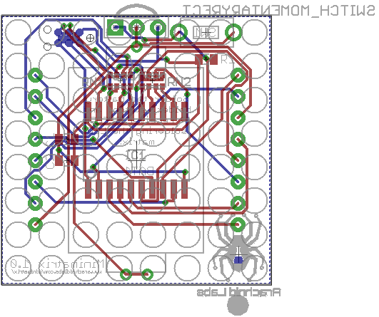
The back of the board - the part that faces out when soldered to a matrix - has all thru-hole parts: the battery holder, IR receiver, and button. The front of the board is all surface mount, and has the microcontroller, resistor arrays, and a couple of decoupling capacitors. The nice thing about this is that once everything’s soldered together, the microcontroller is entirely hidden from view - all you see is a neatly packaged device with battery, button, and display.
There’s a lot of choice out there when it comes to picking LED matrixes, and unfortunately the choice doesn’t stop at form factor and capabilities. There’s absolutely no standard pinout for LED matrices, and few if any of the pinouts make any logical sense, either. Here’s a couple:


While the first one makes marginally more sense, neither is what I’d call a logical arrangement of pins. Fortunately minimatrix only has to care about monocolor LED matrixes, because when you get to bicolor and full color ones, the number of available pinouts explodes exponentially.
Single color LED matrixes come in what is commonly referred to as “common anode” and “common cathode” versions. In a single-color matrix, this notation doesn’t make a lot of sense, so it’s easier to think of it by considering whether rows are anodes or cathodes. It’s unimportant which you choose for a single color matrix, but for multi-color ones, common anode is often easier, since it’s easier to do high powered low-side switching than it is to do high-side switching.
The basic approach to driving an LED matrix like this is well known and not terribly complicated. You scan over rows, and for each one you power the appropriate columns that should be lit for that row, sourcing your data from some sort of frame buffer. This is most easily done inside a timer interrupt; realistically in order to get a nice flicker free display you need to scan the rows around 50 times a second or more; I went with 100, meaning your timer interrupt needs to fire 800 times a second to scan all the rows. Not terribly difficult, even for a low powered MCU like the ATTiny range.
One significant refinement is in the way pins are allocated, as I alluded to above. Note from the schematic that all the columns are driven - in order - from a single port, port B. This is the only port on the ATTiny4313 that has a full 8 pins. Doing things this way has a major advantage when it comes to the speed and efficiency of our code to write data to the display. Instead of having to individually set each bit, we can write an entire column with a single operation by copying straight from our frame buffer to the port. Here’s the core of our timer interrupt routine:
ISR(TIMER0_COMPA_vect) {
	static uint8_t row = 0;

	// Turn off the old row
	PORTD |= PORTD_ROWS;
	PORTA |= PORTA_ROWS;

	// Set the column data
	row = (row + 1) & 0x7;
	PORTB = display[row];

	// Turn on the new row
	ENABLE_ROW(row);
}
As you can see, this is extremely straightforward, and quick to execute. All we do is set the appropriate row bit, increment the row counter, and output the data for that row to port B.
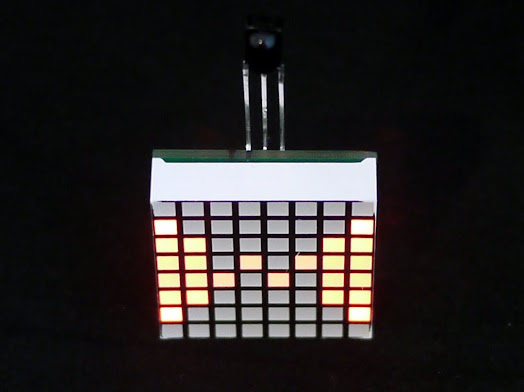
Done? Not quite. Check out this photograph of the minimatrix in action:

Notice how the columns with fewer LEDs on are brighter than the columns with more? That shouldn’t be the case, and at first glance it’s not obvious why it would happen. Check out this chart from the datasheet, though:

That’s showing the voltage on a pin that’s being pulled low, relative to the amount of current it’s sinking. As you can see, the more current it’s sinking, the higher the voltage - consistent with the pin having a nonzero resistance to ground. If we’re sinking 10 milliamps at room temperature, the voltage on the pin will be about 0.3 volts. Since our supply voltage is only 3 volts, and the forward voltage drop on our LEDs is about 2 volts, that means our LED just got about 30% dimmer!
The solution to this is reasonably straightforward. Instead of setting a single timer interrupt for display refresh, we set two. The first turns the LEDs on as above. Then, it calculates a delay based on the number of lit LEDs in the column, and sets the delay until the second timer interrupt accordingly. This second timer interrupt turns the LEDs off - effectively, dimming the display so that all rows are the same brightness as one with all its LEDs lit. This is perhaps the only practical use I’ve ever encountered for all those bit manipulation hacks for counting set bits
Before settling on IR, I experimented with a couple of options for allowing users to program messages and animations into the minimatrix. One I spent a lot of time on was programming using computer monitors and light detectors, like these projects did. It’s not even necessary to add light sensors, since the LED matrix can be used for that purpose.
Sensing light using an LED is pretty simple. Reverse bias the LED - set the cathode high and the anode low - then stop driving one of them and wait to see how long it takes it to change state. The more light is shining on the LED, the faster the anode will go high (or the cathode, low). If all you care about is a digital threshold, you can pick a delay that distinguishes the two light levels you care about, wait that long, and then do a single check.
In principle, the LED matrix can be used the same way. It even ought to be possible to have an entire matrix of sensors, by selectively reverse biasing rows and then testing columns, or vice versa. In practice, I had a lot of issues with this causing what appeared to be crosstalk - both electrical and optical - between rows and columns. I was able to use entire rows as a single sensor with some degree of reliability, but that was about it.
A further problem with this approach is speed. For light levels emitted by a typical computer monitor, you need to wait between about 5 and 20 milliseconds for each sense, which gives you a realistic upper bitrate of about 50 bits per second - less than spectacular. You can attempt to use multiple channels, but then you run into the crosstalk issues I alluded to above.
Given the low bitrate, reliability, and crosstalk issues, I decided to move on. Fortunately, IR is a whole different ballgame.
#IR decoding There’s a number of IR encoding schemes for remote controls out there. Some of the more popular ones are RC-5, NEC and Sony SIRC. All of them use on-off keying with a carrier wave in the range of 36-40KHz - most commonly 38KHz. What this means is that they emit a series of pulses at 38KHz for ‘on’, and no pulses for ‘off’. This is easily detected and decoded by common IR receiver components, so the signal the microcontroller gets is a logic low when a carrier wave is present, and a logic high when it isn’t.
The protocol used by the remote controls I’m using, and the one I decided to go with, is RC-5. This is a fairly straightforward protocol. Each message is 14 bits long, consisting of a start bit, a ‘field’ bit, a ‘toggle’ bit, a 5 bit device address, and a 6 bit command. There’s no checksumming or error correction.
All of this data is transmitted using manchester encoding. Manchester encoding works by splitting each bit up into two half-bits. A 0 is represented by the sequence 10, while a 1 is represented by the sequence 01. The purpose of this is to ensure regular transitions in the data stream, which makes it practical for the receiver and transmitter to stay in sync with each other.

While manchester encoding’s very simple in principle, figuring out the best way to decode it took me an embarrassingly long time. Using an interrupt or polling based system, each time the signal goes from 1 to 0 or 0 to 1, you know how long it’s been since the last transition - but how do you extract the datastream from that? I’d recommend stopping and thinking about the problem before you read on - see if you arrive at the same solution I did!
Ready? Okay.
The important insight with manchester encoding is that there is a transition in the middle of every bit. If the transition is high to low, the bit being transmitted is a 0, if the transition is low to high, the bit being transmitted is a 1. All we have to do now is identify which transitions are in the middle of bits (the ones we care about) and which are between bits (which we can discard).
Fortunately, this is really easy to do. Since we’re already timing the interval since the last transition, simply check that when we get a transition. If it’s about half a bit interval - 889 microseconds in the case of RC5 - ignore the transition, and keep counting, since we know it’s an inter-bit transition. Any other transitions are logically those corresponding to bits, and we simply observe the direction of the transition to decode the data. Simple!
In the current minimatrix firmware, this is done with a timer interrupt, but with the new schematic and PCB, this can be done with an interrupt - which has the additional benefit of making it possible to wake the minimatrix up from power down mode with IR commands.
Another challenge in building LED matrix displays is how to display text. Typically a bitmap font is used for this, with a common size being 7x5 pixels. The font can be stored as constant data in a C file and compiled straight into the firmware. There aren’t a great deal of good options out there, and the best one I found is Adafruit’s glcdfont. This is a 7x5 bitmap font, represented as 5 bytes for each glyph; each byte corresponds to a column, which lines up very conveniently with minimatrix’s column addressing. Thus, when handling text, each time we need to scroll a new column into view, we look up the relevant column of the current glyph in the font array, and simply write that byte to the frame buffer. Simple, and quick.
Currently, minimatrix embeds the entire glcdfont in firmware, all 256 glyphs. This uses up a fair chunk of flash - 1280 bytes out of the 4k available - so it’s distinctly possible that it’ll be cut down to just the 128 or even 96 most useful glyphs in future, as we try to cram more features in.
Another alternative is a proportional font, which has a couple of advantages. It looks substantially nicer, since ‘i’ and ‘l’ and so forth no longer take up the same with as ‘m’ and ‘w’. It also allows for having ‘dingbat’ or ‘icon’ glyphs in the font which are wider than a typical glyph, up to the full 8 columns. There’s two main disadvantages: First, it will require more memory, not less, to store the indexing information required to look up variable width characters. Second, I haven’t been able to find any variable width bitmap fonts! This is why one of the stretch goals for the minimatrix fundraiser is to commission such a font, and open-source it, which I believe will be a benefit to anyone wanting to do this sort of text display.
Also, if anyone has any ingenious ideas on how to represent a proportional font in as little memory as possible, I’d be very keen to hear them.
Minimatrix’s approach to storing and displaying data is straightforward. Text and animations are stored in EEPROM, of which the 4313 has 256 bytes. The first few bytes are a header, specifying what type of data it is, and other important information, like the scroll speed or frame rate, and the number of frames in the case of animations. 256 bytes is enough for about 248 characters of text data, or 31 frames of (uncompressed) animation.
Currently, minimatrix has two graphics and storage modes: marquee text, and raw framebuffer animation. A tool is provided in the github repository to convert 8x8 2 bit gifs into the format used for animation. I’d like to implement more graphics modes, and contributions from others along these lines are very welcome.
I’d very much like to see contributions from others to the minimatrix firmware. Send a pull request to the github repository with a feature, bugfix or enhancement, and I’ll send you a free one in the mail. Easy!
Of course, Minimatrix is open source hardware, and the firmware is open source too. Check it out in the github repository.
I’m currently running a fundraiser for minimatrix on Tindie, and you can get one for just $12.50 with an IR remote, or $10 without. The LED matrix manufacturer has a high minimum order quantity, so I’m hoping there’s enough interest to justify doing a run of them.