
A while ago I found myself in need of a dummy load for testing a power supply, and was surprised to find that there weren’t any good kits around for this. On the commercial end of things, dummy loads tend to be large, powerful, and incredibly expensive. There’s a few hobbyist projects out there, but they tend to fall into two categories: absurdly overcomplicated and expensive, or unavailable. So I set out to design and build my own, hopefully solving the problem for everyone.
Re:load is an adjustable constant-current load with several key properties:
Most DIY adjustable loads use regular FETs or BJTs as the main pass elements, but this made me nervous. These devices don’t have any overtemperature protection built in, so they’ll happily self-destruct if you put too much power through them. For me that just seemed like a matter of time. After a lot of searching, I found the BTS117 and BTS141 “Smart low side switch” ICs. These remarkable little devices have built in ESD, overcurrent, overvoltage, and overtemperature protection, making them ideally suited for a dummy load. They act just like regular FETs, too, making them easy to interface with.
The basic circuit for building a constant current load is pretty straightforward.

The FET is drain is connected to the positive rail, and its source is connected to one end of a shunt resistor. The other end of the shunt resistor goes to the ground rail. This forms the main current path for the dummy load. The FET’s gate is connected to the output of an opamp, and the negative input of the opamp is connected to the junction between the FET source and the shunt resistor. This forms a feedback loop: the opamp will adjust the voltage on the FET’s gate to ensure the voltage across the sense resistor is the same as the voltage on its positive terminal. Since the voltage across the sense resistor is proportional to the current flowing through it (and thus the FET), the result is a constant current load. Presto!
In order to be able to adjust the current, we connect the opamp’s positive terminal to a voltage divider made of a potentiometer and a fixed resistor. Selecting the value of these correctly allows us to vary the load current over the desired range linearly as we turn the potentiometer.
A regulated supply is necessary for all this to work, of course, and I’ve gone with the LP2950. This little 3-terminal regulator supplies up to 100mA - way more than we need for our opamp and voltage divider - with remarkably good regulation.
The choice of opamp is quite important here. We need something that can handle input voltages near the ground rail, provide output voltages near the positive rail, and have low offset voltage for accurate operation. After a bit of searching, the MCP6002 turns out to be a good choice. Its input offset voltage is 4.5mV - equivalent to about 100mA of current across the dummy load in our configuration. It can handle input voltages right down to the negative rail, and produces output voltages within 25 millivolts of the positive rail. It’s also affordable, making it perfect for our application.
Since the IC has two opamps in it, we may as well put the other to use. A couple of resistors allows us to provide a test point for checking the load current with your multimeter in voltage mode - 1 amp corresponds to 0.1 volts.
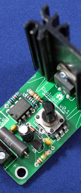
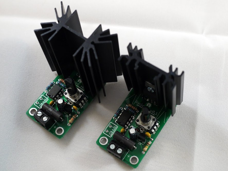
Laying out the PCB was an interesting task. After working with SMD parts for so long, thru-hole parts seem huge. I came up with a design I’m quite happy with on a 3cm x 5cm footprint:
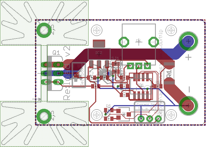
The heatsink is a standard footprint that can be soldered directly onto the PCB. Variants are available in different sizes and thermal capacities, too.
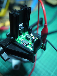
After the PCBs arrived, testing and qualifying it was a fun exercise. As I’d hoped, despite my best efforts I’m unable to destroy it. The thermal shutdown cuts in smoothly when it goes overtemperature; reverse polarity draws a lot of current from the power supply through the FET’s body diode but otherwise does no damage.
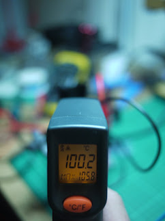
After a dab of thermal paste, the heatsinks perform rather well too. The smaller one handles 12W continuous, while the larger one can handle 20W of power dissipation.
So what would you do with a re:load? You could use it as I am - to test a power supply. Hook it up to a constant voltage supply to turn it into a constant current supply for electroplating, to test out a high power LED, or for other purposes. Or hook it up in winter for a bit of extra heat.
If you’re interested in a re:load to call your own, they’re available as kits on Tindie.
Naturally, the whole project is OSHW. Get the complete schematics to build your own here.